(China (Mainland))


Product Summary
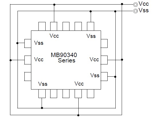
The MB90349CA with up to 2 FULL-CAN interface and FLASH ROM is especially designed for automotive and other industrial applications. The main features of the MB90349CA are the on-board CAN Interfaces, which conform to V2.0 Part A and Part B, while supporting a very flexible message buffer scheme and so offering more functions than a normal full CAN approach. With the new 0.35 mm CMOS technology, Fujitsu now offers on-chip FLASH-ROM program memory up to 512 Kbytes. The power supply (3 V) of the MB90349CA is supplied to the internal MCU core from an internal regulator circuit. This creates a major advantage in terms of EMI and power consumption. The internal PLL clock frequency multiplier of the MB90349CA provides an internal 42 ns instruction cycle time from an external 4 MHz clock.
Parametrics
MB90349CA absolute maximum ratings: (1)Maximum Clamp Current ICLAMP: -4.0 +4.0 mA; (2)Total Maximum Clamp Current S|ICLAMP|: 40 mA; (3)level maximum output current IOL: 15 mA; (4)level average output current IOLAV4 mA; (5)level maximum overall output current SIOL: 100 mA; (6)level average overall output current SIOLAV: 50 mA; (7)level maximum output current IOH: -15 mA; (8)level average output current IOHAV: -4 mA; (9)level maximum overall output current SIOH: -100 mA; (10)level average overall output current SIOHAV: -50 mA; (11)Power consumption PD: 340 mW MB90F347; (12)Operating temperature TA: -40 +105 ℃; (13)Storage temperature TSTG: -55 +150 ℃.
Features
MB90349CA features: (1)16 Mbyte CPU memory space; (2)Instruction system best suited to controller; (3)Instruction system compatible with high-level language (C language) and multitask; (4)Increased processing speed; (5)Powerful interrupt function; (6)Automatic data transfer function independent of CPU; (7)Low power consumption (standby) mode; (8)Full-CAN interface : up to 2 channels; (9)UART (LIN/SCI) : up to 4 channels; (10)I2C interface: up to 2 channels (devices with C-suffix only); (11)DTP/External interrupt : up to 16 channels, CAN wakeup : up to 2 channels; (12)Delay interrupt generator module; (13)8/10-bit A/D converter : 16/24 channels.
Diagrams
 |
 MB90050 |
Other |
|
Data Sheet |
Negotiable |
|
||||
|
MB90091A |
Other |
|
Data Sheet |
Negotiable |
|
||||
|
MB90092 |
Other |
|
Data Sheet |
Negotiable |
|
||||
|
MB90096 |
Other |
|
Data Sheet |
Negotiable |
|
||||
|
MB90097 |
Other |
|
Data Sheet |
Negotiable |
|
||||
|
MB90098A |
Other |
|
Data Sheet |
Negotiable |
|
||||